[email protected]
86-18692697905


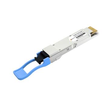
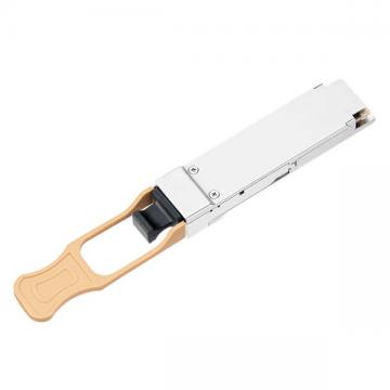
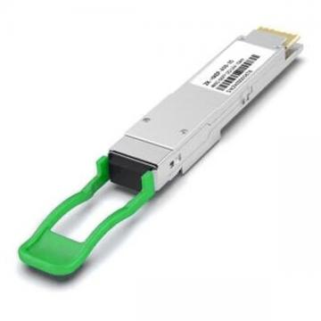
| NVIDIA Compatible: | MMS1W50-HM | Vendor Name: | Fibercoms | Form Factor: | QSFP56 |
| Max Data Rate: | 212.5Gbps | Wavelength: | 1271nm, 1291nm, 1311nm, 1331nm | Max Distance: | 2km |
| Connector: | Duplex LC | Cable Type: | SMF | Voltage Supply: | 3.3V |
| Modulation Format: | PAM4 | Host Required: | FEC | DDM Support: | Yes |
| Transmitter Type: | EML CWDM4 | Receiver Type: | PIN | Operation Temperature: | 15 to 65°C (59 to 149 °F) |
| Protocols: | QSFP56 MSA, IEEE 802.3bs, 200GBASE-FR4 | Warranty: | 3 Years | Maximum Power: | < 6.5W |
Absolute Maximum Specifications
Absolute maximum ratings are those beyond which damage to the device may occur
| Parameter | Min | Typical | Max | Units |
| Storage Temperature | Ts | -40 | 85 |
°C
|
| Relative Humidity(non-condensing) | RH | 15 | 85 | % |
| Supply Voltage | Vcc | -0.5 | 3.6 | V |
Optical Transmitter Specifications
| Parameter | Min | Typical | Max | Unit | Notes |
| Signaling rate(each lane (range) | 26.5625± 100 ppm | GBd | |||
| Modulation format | PAM4 | ||||
| Lane wavelength(range) |
1264.5 1284.5 1304.5 1324.5 |
1271 1291 1311 1331 |
1277.5 1297.5 1317.5 1337.5 |
nm | |
| Side-mode suppression ratio (SMSR) | 30 | dB | |||
| Total average launch power | 10.7 | dBm | |||
| Average launch power, each lane | 4.7 | ||||
| Average launch power, each lane | -4.2 | dBm | 1 | ||
|
Difference in launch power between any two lanes (OMAouter) max |
4 | dB | |||
|
Outer Optical Modulation Amplitude(OMAouter), each lane |
-1.2 | 4.5 | dBm | 2 | |
| Launch power in OMAouter minus TDECQ , each lane | -2.5 | dBm | |||
|
Transmitter and dispersion eye closure for PAM4(TDECQ), each lane |
3.3 | dB | |||
| Average launch power of OFF transmitter, each lane | -30 | dBm | |||
| Extinction ratio | 3.5 | dB | |||
| RIN17.10MA | -132 | dB/Hz | |||
| Optical return loss tolerance | 17.1 | dB | |||
| Transmitter reflectance | -26 | dB | 3 | ||
Optical Receiver Specifications
| Parameter | Min | Typical | Max | Units | Notes |
| Signaling rate(each lane(range) | 26.5625± 100 ppm | GBd | |||
| Modulation format | PAM4 | ||||
| Lane wavelength(range) |
1264.5 1284.5 1304.5 1324.5 |
1271 1291 1311 1331 |
1277.5 1297.5 1317.5 1337.5 |
nm | |
| Damage threshold, each lane | 5.7 | dBm | 4 | ||
| Average receive power, each lane | 4.7 | dBm | |||
| Average receive power, each lane | -8.2 | dBm | 5 | ||
|
Difference in receive power between any two lanes (OMAouter) |
4.1 | dB | |||
| Receiver reflectance | -26 | dB | |||
| Receiver sensitivity(OMAouter), each lane | -6.5 | dBm | 6 | ||
| Stressed receiver sensitivity(OMAouter), each lane | -3.6 | dBm | |||
| Conditions of stressed receiver sensitivity test: (note 5) | |||||
| Stressed eye closure for PAM4(SECQ), lane under test | 3.3 | dB | |||
| OMAouter of each aggressor lane | 0.5 | dBm | |||
| LOS De-Assert | -9 | dBm | |||
| LOS De-Assert | -22 | -12 | dBm | ||
| LOS Hysteresis | 0.5 | dB | |||
Notes:
Key Features:
Shenzhen Fibercoms Co., Ltd
Phone:
86-18692697905
Email:
[email protected]
Address:
Hubei road, Dongmen Street, Luohu District, Shenzhen, China